

IEC 60068-2-14 Nb: Rapid Temperature Cycling for DRAM Module Reliability
Publish Time:2026-09-02Views:()
Test Standard: IEC 60068-2-14 Test Nb — Change of Temperature with Specified Rate of Change
DRAM modules are the working memory of virtually every computing system on the planet. From data center servers to automotive infotainment systems, DRAM operates under continuous thermal stress — power-on heating, active load thermal transients, and ambient temperature fluctuations. Unlike thermal shock, which tests survival under extreme transitions, rapid temperature change testing (Test Nb) evaluates how DRAM modules perform under realistic but accelerated thermal cycling rates.
Why DRAM Modules Are Vulnerable to Thermal Cycling
A DRAM module is a multi-component assembly: DRAM dice on a PCB substrate, decoupling capacitors, SPD EEPROM, and a heat spreader (in high-performance modules). Each component has a different thermal mass and CTE:
· Silicon die: CTE ~3 ppm/°C
· PCB substrate (FR-4): CTE ~14-17 ppm/°C (in-plane), ~50-80 ppm/°C (z-axis)
· Solder joints (SAC305): CTE ~21 ppm/°C
· Copper traces: CTE ~17 ppm/°C
Under temperature cycling, the CTE mismatch between the DRAM die and the PCB substrate generates shear stress at every solder ball. Over hundreds or thousands of cycles, this stress causes solder joint fatigue — crack initiation at the solder ball-package interface, propagation through the solder joint, and eventual electrical open.
For DRAM modules specifically, the failure modes under thermal cycling include:
· Solder ball cracking: The #1 failure mode, particularly at corner balls where mechanical stress is highest
· Capacitor cracking: MLCC decoupling capacitors are brittle and crack under thermal stress
· PCB delamination: Z-axis CTE mismatch can cause barrel cracking and via failure
· DRAM die edge cracking: Especially in thinned die used in high-density packages
IEC 60068-2-14 Test Nb: Controlled-Rate Temperature Cycling
Test Nb specifies temperature cycling at a controlled rate of change, as opposed to Test Na which specifies rapid transitions. The key parameters are:
· Temperature extremes: Typically -40°C to +85°C (industrial) or -55°C to +125°C (automotive)
· Rate of change: 1°C/min to 15°C/min (typically 5-10°C/min for DRAM testing)
· Dwell time: Sufficient for thermal stabilization, typically 15-30 minutes per extreme
· Number of cycles: 100-1000+ depending on qualification level
Test Nb is particularly relevant for DRAM because it simulates the thermal cycling that occurs during actual product use — power-on/power-off cycles, workload variations, and ambient temperature changes — but at an accelerated rate.
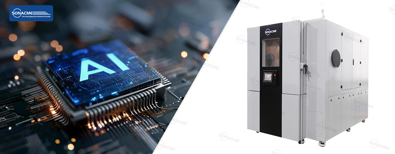
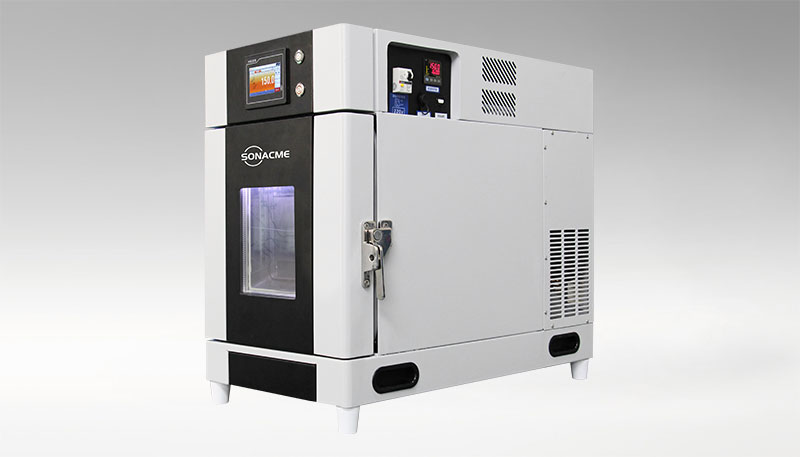
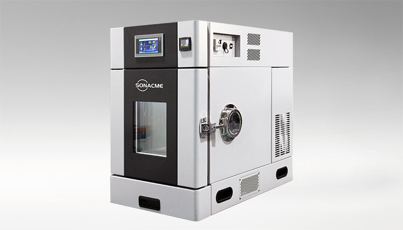
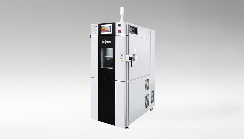
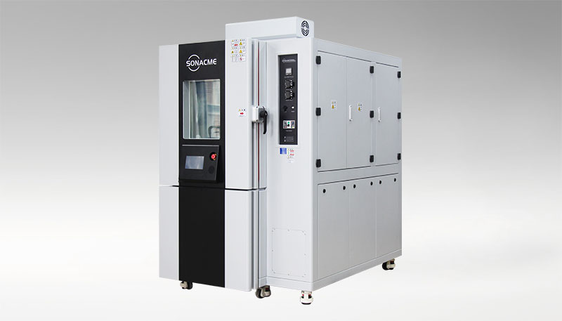
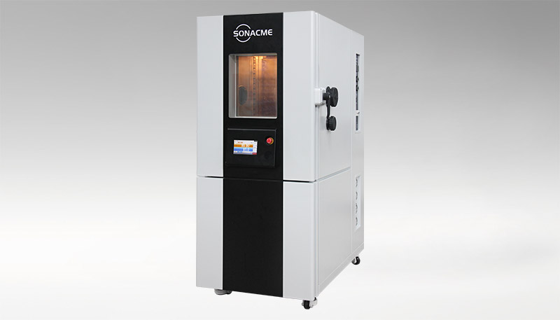
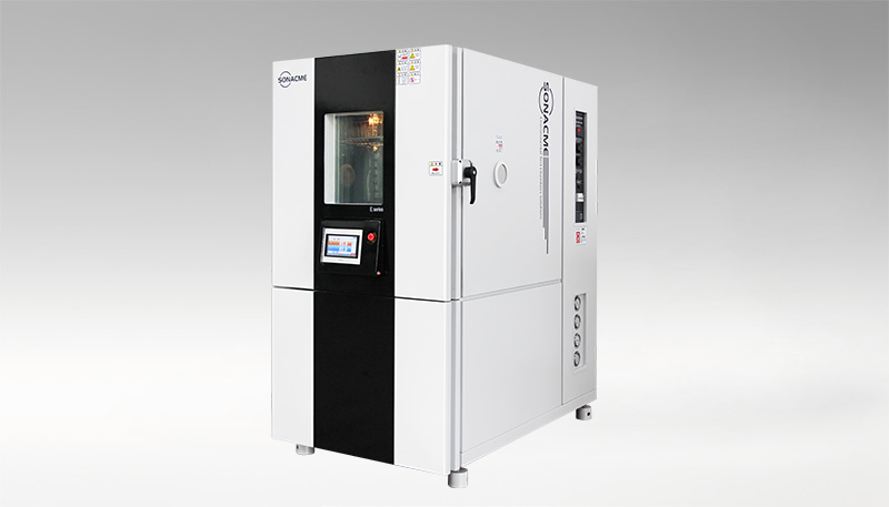
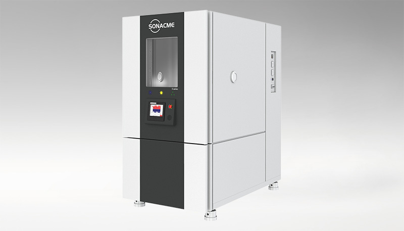
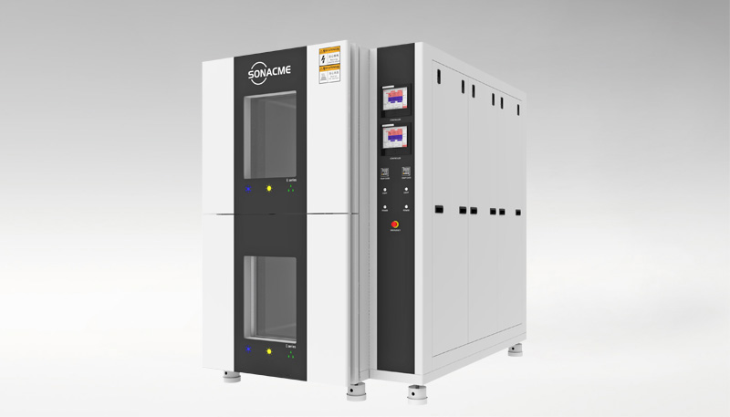
SONACME Rapid Temperature Change Test Chamber: Engineered for Test Nb
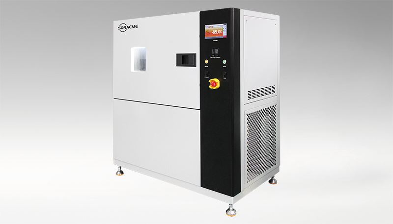
SONACME's Rapid Temperature Change Test Chamber is specifically designed to deliver the precise, programmable temperature change rates that Test Nb requires. With change rates of 15K/min, 20K/min, and 25K/min available, the chamber can accommodate the full spectrum of Test Nb applications.
Key Technical Parameters:
Parameter | Specification |
Temperature Change Rate | 15K/min, 20K/min, 25K/min (model dependent) |
Temperature Range | Meets IEC 60068-2-14 Nb requirements |
Humidity Control | Wide temperature and humidity range |
Heat Load Support | Yes — accommodates powered specimens |
Standards Compliance | IEC 60068-2-14 Nb, IEC 60068-2-30, IEC 60068-2-38 |
Controller | SONACME self-developed, programmable |
Energy Saving | LOW GWP technology, up to 40% energy saving, R-449A refrigerant |
The chamber's ability to support heat load is critical for DRAM testing — modules are often tested under powered conditions to simulate real operating thermal profiles. The wide humidity range enables combined temperature-humidity cycling per IEC 60068-2-38 when needed.
DRAM Thermal Cycling Test Protocol
A recommended Test Nb protocol for DRAM module qualification:
1. Sample size: 30-77 modules per lot (per JEDEC JESD47)
2. Temperature extremes: -40°C to +95°C (covering industrial and automotive ranges)
3. Change rate: 10°C/min (representative of power cycling rates)
4. Dwell time: 30 minutes at each extreme (ensures thermal equilibration of the module)
5. Cycle count: 500 cycles for commercial qualification; 1000+ for automotive (AEC-Q100)
6. Interim testing: Functional test at room temperature every 100 cycles
7. Post-test: Full functional test + boundary scan + visual inspection
The SONACME controller's programmable interface allows automated execution of the entire 500-1000 cycle test with interim pause points for electrical testing — reducing operator intervention and ensuring test consistency.
Why Rapid Temperature Change Testing Is Essential for DRAM
The DRAM industry is moving toward higher densities (DDR5 64Gb), higher speeds (DDR5-6400 and beyond), and smaller form factors (LPDDR5X in mobile). These trends increase power density, thermal stress, and the risk of solder joint fatigue. Additionally, the automotive DRAM market is growing rapidly — ADAS systems, infotainment, and autonomous driving platforms all demand DRAM that survives thousands of thermal cycles under harsh conditions.
IEC 60068-2-14 Test Nb, executed on a SONACME Rapid Temperature Change Test Chamber, provides the controlled, accelerated thermal cycling environment that DRAM manufacturers need to qualify their products for these demanding applications.
Contact SONACME Technology to discuss your DRAM thermal cycling test requirements.
Latest News
-
JESD22-A104 Temperature Cyc...
IEC 60068-2-14 Nb rapid temperature change testing g...
-
MIL-STD-810 Method 503 Ther...
IEC 60068-2-14 Nb rapid temperature change testing g...
-
IEC 60068-2-14 Na/Nb Testin...
IEC 60068-2-14 Nb rapid temperature change testing g...
-
JEDEC JESD22-A106 Complianc...
IEC 60068-2-14 Nb rapid temperature change testing g...
-
Meeting ISO 26262 Standards...
IEC 60068-2-14 Nb rapid temperature change testing g...
-
IEC 60068-2-38 Environmenta...
IEC 60068-2-14 Nb rapid temperature change testing g...
+86-180 2704 9206
Tel:+86(0769)83234966
E-Mail:info@sonacme.com
Contacts:Marcia/+86-180 2704 9206
Add:Building 7, No.310 Songbai Road, Liaobu Town, Dongguan City, Guangdong


 +86-180 2704 9206
 WhatsApp:+86-180 2704 9206
 info@sonacme.com